A 3 phase motor symbol is a circle containing the letter M with the notation 3~ placed beside it, following IEC 60617. The same motor on a NEMA-style drawing appears as a circle labelled MOTOR with a 3 PH note. In both cases, it is the standard schematic way of saying that the load connected to three supply lines is an alternating-current motor designed for three-phase power.
On any industrial drawing, this symbol anchors the power circuit. It tells you that three phase conductors feed the device, but it does not show the frame size, horsepower, enclosure type, or efficiency class. Those details come from the nameplate and the equipment schedule, not from the symbol itself. Knowing what the symbol does and does not convey prevents expensive misreading when you buy, install, replace, or repair motors.
What Is the 3 Phase Motor Symbol?
A 3 phase motor symbol is a standardised graphic shorthand used on electrical diagrams to represent a three-phase alternating-current motor. In IEC 60617, the motor is drawn as a circle with the letter M for motor and a tilde for alternating current; the digit 3 in front of the tilde indicates a three-phase supply. In NEMA and ANSI practice, the same device appears as a circle containing the word MOTOR, with an adjacent note such as 3 PH or 3-PHASE.
| Element | IEC 60617 convention | NEMA / ANSI practice |
|---|---|---|
| Basic symbol | Circle with letter M | Circle with MOTOR or M |
| AC indication | Tilde (~) beside M | Assumed; phase note added |
| Phase designation | 3~ | 3 PH or 3-PHASE |
| Terminal labels | U1, V1, W1 and U2, V2, W2 | T1, T2, T3; extra digits for part-winding or two-speed motors |
| Winding connection | Y or DELTA note beside symbol | Text note WYE or DELTA |
Both conventions identify the same physical item: an induction motor started and run from a three-phase supply. The difference matters most when a drawing is prepared by an engineer trained to one standard and the connected equipment follows the other.
Standard Symbol Variants You Will Encounter
IEC 60617 Symbol
In IEC drawings, the basic symbol is a circle with the letter M and a 3~ annotation. If the motor is a squirrel-cage induction machine, you may see a small gap or a solid segment added to the circle; if it is a slip-ring or wound-rotor machine, three short lines representing the rotor connections are drawn. When the drawing includes a contactor and an overload relay, the motor symbol sits at the end of the three phase lines, downstream of those protective devices.
NEMA / ANSI Symbol
NEMA-style diagrams usually label the motor more explicitly. The circle may contain the full word MOTOR, and the phase count is written as 3 PH. Squirrel-cage motors are sometimes marked SC, and wound-rotor motors WR. Because NEMA drawings dominate North American panel and equipment documentation, this variant appears on a large share of existing industrial drawings.
Squirrel-Cage vs Wound-Rotor Indicators
The fastest way to distinguish the two rotor types is to look for extra connection lines. A squirrel-cage rotor needs no external rotor circuit, so no extra lines leave the symbol. A wound-rotor motor has slip-ring leads, so three additional conductors are drawn. Confusing the two changes the entire replacement decision: a wound-rotor motor requires an external resistor bank and a different starter, while a squirrel-cage motor connects directly to a contactor.
How to Read the Symbol in Circuit Diagrams
The meaning of the symbol depends on where it appears. In a power diagram, the three-phase motor symbol is drawn on the three vertical lines that represent phases L1, L2, and L3, with the contactor and overload relay in series. In a control diagram, the motor appears indirectly through the contactor coil, the overload auxiliary contact, and the start and stop pushbuttons. Beginners often search for a motor symbol inside the control circuit and find none, because the motor is always represented in the power circuit.
Terminal and Connection Notes
The symbol rarely shows the winding connection inside the circle; the connection is specified next to it. A star-connected motor shows the note Y, a delta-connected motor shows the note DELTA, and a star-delta starter drawing shows both positions. Terminal markings must follow the same standard: IEC machines use U1, V1, W1 for the first set and U2, V2, W2 for the second set; NEMA machines use T1, T2, T3, and T4, T5, T6 when six leads are involved.
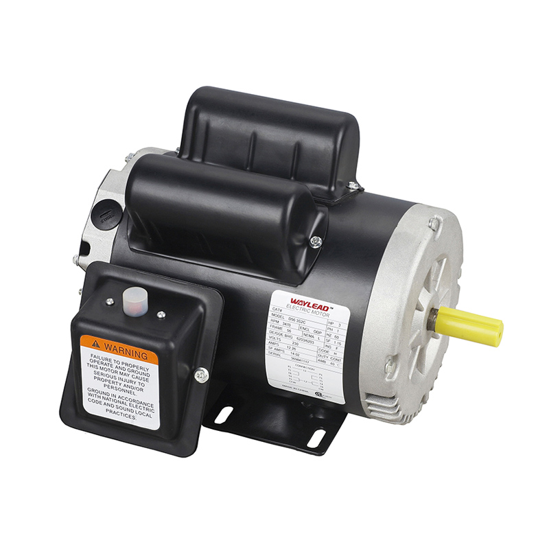
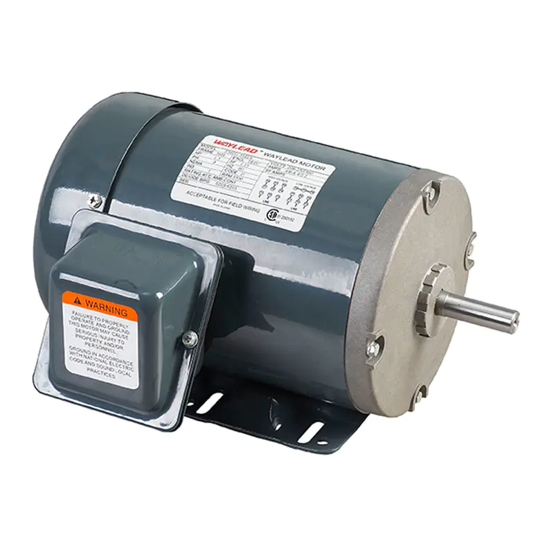 56 Frame Three-Phase Four-in-One Motor with C FlangeThis rolled-steel-frame motor offers a 1.15 service factor and F-class insulation, making it a compact option worth checking when referencing motor nameplate details against schematic symbols.View Product →
What the Symbol Does Not Tell You
No schematic symbol conveys the rated power, speed, voltage, enclosure, or efficiency class. A drawing may show a generic three-phase motor when the actual machine is a TEFC premium-efficiency motor, a brake motor, or a pump motor with dedicated shaft dimensions. For procurement, you must cross-reference the symbol position with the equipment schedule and the motor nameplate.
Common Mistakes When Reading the Symbol
Most mistakes happen when the drawing and the physical machine do not match. The list below covers the ones we see most often in the field.
- Reading a plain circle with M as a three-phase motor. Without a 3~ or 3 PH note, the symbol is an unspecified motor; single-phase diagrams often use the same circle with a 1~ note.
- Mixing terminal standards. Connecting a NEMA motor that has T-marked leads to an IEC diagram that expects U, V, W labelling can reverse rotation or bypass overload protection.
- Assuming the rotor type from the basic symbol. Cage and wound-rotor versions look similar; always check for extra rotor leads.
- Ignoring the winding connection note. A motor designed for delta operation can be damaged if it is connected in star at full line voltage.
- Copying a symbol without verifying the phase count on the equipment schedule, which leads to ordering a single-phase motor for a three-phase circuit.
Most of these mistakes surface only during commissioning, when a motor fails to start, runs backwards, or overheats. A few seconds spent checking the symbol against the nameplate saves an entire troubleshooting cycle.
Why the Symbol Matters for Motor Buyers and Maintenance Teams
For purchasing and maintenance staff, the 3 phase motor symbol is the bridge between the drawing and the physical machine. When a motor fails, the replacement must respect the connections shown on the drawing: voltage, start method, and terminal count must match the original. This is why many OEM specifications include the terminal configuration directly beside the schematic.
As a manufacturer of NEMA and IEC three-phase motors, we see the practical consequences of symbol misreading every year. A buyer orders a single-phase motor for a three-phase circuit, or requests a 56-frame motor when the drawing clearly specifies a TEFC premium-efficiency unit. Reading the symbol correctly and then matching it to the nameplate data remains the most reliable way to avoid these mismatches.
If you are still comparing motor types, our review of the advantages of using a three-phase motor explains the efficiency, torque, and cost differences in practical terms.
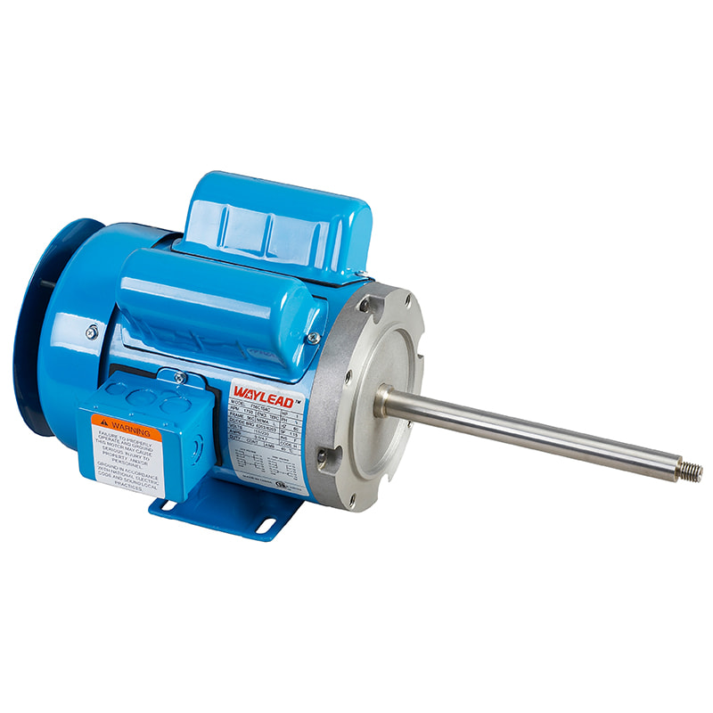
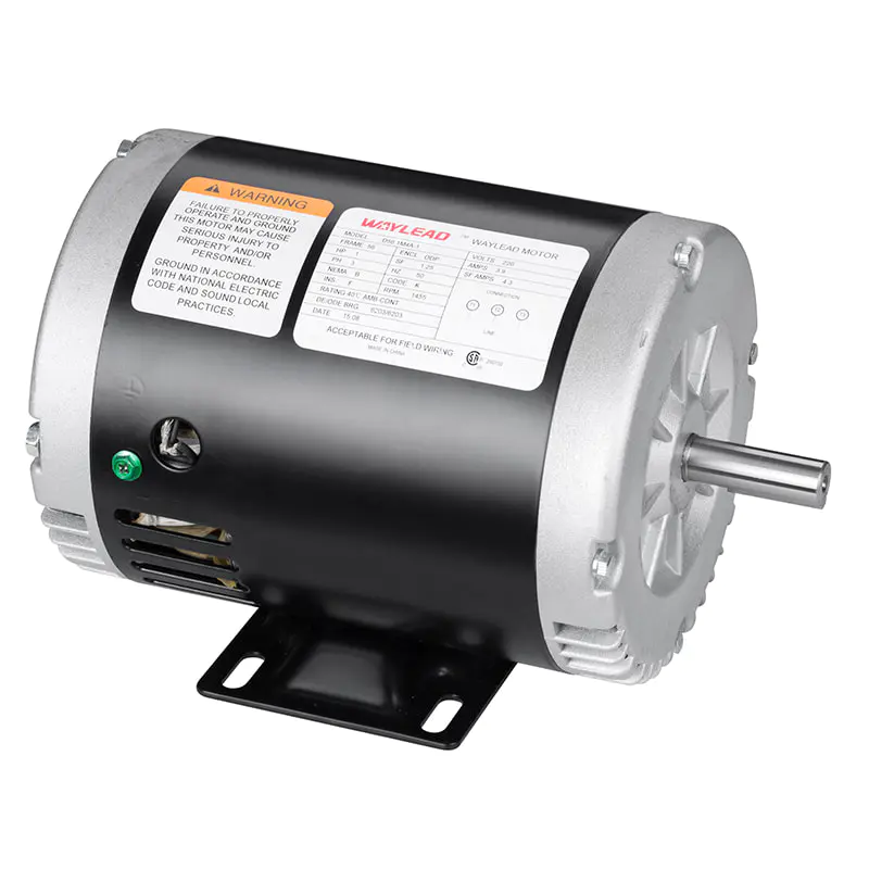 Three-Phase Fractional Horsepower Premium Efficiency MotorWith CSA, CUS, and UL certification and a 1.15 service factor, this fractional-horsepower motor suits applications like fans and pumps, reinforcing the practical benefits of three-phase design discussed above.View Product →
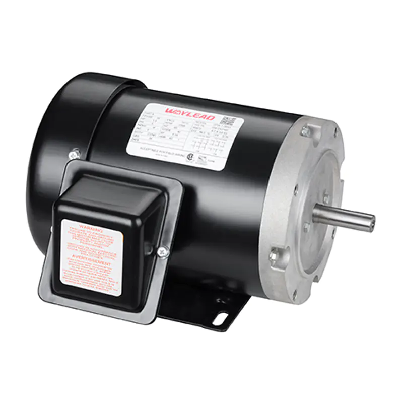
 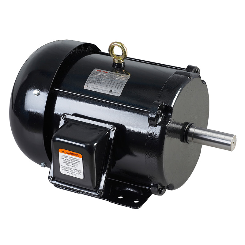 Three-Phase Totally Enclosed High-Efficiency MotorThis totally enclosed motor carries EPACT and CSA/CUS/UL certifications with F-class insulation, making it a reliable choice when confirming efficiency and enclosure details that schematic symbols omit.View Product →
Frequently Asked Questions
What does the 3~ notation mean on a motor symbol?
3~ means three-phase alternating current. The tilde denotes AC, and the digit 3 indicates that three phase conductors supply the motor. It is the IEC abbreviation for a three-phase AC machine.
How do I tell a single-phase and a three-phase motor symbol apart?
Look at the phase notation. A three-phase symbol carries 3~ in IEC drawings or 3 PH in NEMA drawings; a single-phase symbol carries 1~ or 1 PH. The bare circle with M does not specify the phase count.
Does the symbol indicate the efficiency class or frame size?
No. The symbol only identifies the machine as a three-phase AC motor. Efficiency class, frame size, horsepower, and enclosure type are listed on the nameplate and in the equipment data sheet.
Is a brake motor drawn differently?
Brake motors use the same three-phase motor symbol. The brake actuator coil is drawn separately in the control circuit, and the motor circle keeps the same M and 3~ notation.
Why do some drawings show six terminals on the motor symbol?
Six terminals mean the winding can be connected in either star or delta. The drawing shows U1, V1, W1 and U2, V2, W2 (IEC) or T1 to T6 (NEMA), and the connection diagram determines which configuration is used.
The 3 phase motor symbol is one of the most common notations in industrial electrical documentation and one of the most frequently misread. A circle with M and 3~, or MOTOR with 3 PH, always points to a three-phase AC machine. Everything else belongs to the nameplate and the connection notes.
Keep the terminal designations and the star-delta note in view, and you will order, wire, and maintain the right motor every time. For more reference material on motor selection and maintenance, visit the Waylead Motor knowledge base and browse the product and news sections.